IG Electronics
Currency
0
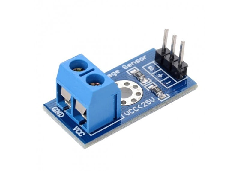
Voltage Sensor Module

Voltage Sensor Module

BD 7.500

Voltage Detection Sensor Module is a simple and very useful module that uses a potential divider to reduce any input voltage by a factor of 5. This allows us to use the Analog input pin of a microcontroller to monitor voltages higher than it capable of sensing. For example, with a 0V - 5V Analog input range, you are able to measure a voltage up to 25V. This module also includes convenient screw terminals for easy and secure connections of a wire.

The internal circuit diagram of the Voltage Sensor Module is given below.

Voltage Detection Sensor Internal Circuit

The voltage circuit consists of a voltage divider circuit of two resistors in which R1 is 30K and R2 is 7.5K.


How to Use Voltage Sensor Module with Arduino

Interfacing a voltage sensor with Arduino or any other microcontroller is pretty straight forward. Connect the VCC and GND of voltage source whose voltage to be measured to the screw terminals of the voltage sensor. Connect the S and – (GND) pins of voltage sensor to Analog pin and GND of Arduino respectively.

Input and output voltage can be calculated using:

Vin = Vout * (R2/(R1+R2)) Here R1 = 30K ohm and R2 = 7.5K ohm Vout = (analogvalue * 5 / 1024).

Arduino Voltage Sensor Module Circuit Working

    Choose Quantity
    + Add to Cart
    Product Details
    Items have been added to cart.
    One or more items could not be added to cart due to certain restrictions.
    Added to cart
    - There was an error adding to cart. Please try again.
    Quantity updated
    - An error occurred. Please try again later.
    Deleted from cart
    - Can't delete this product from the cart at the moment. Please try again later.