IG Electronics
Currency
0
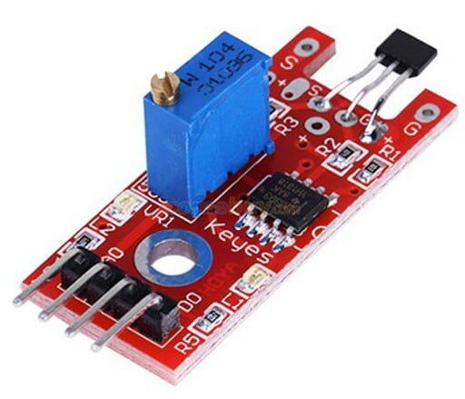
Hall Magnetic Linear Sensor Module

Hall Magnetic Linear Sensor Module

Non-returnable
BD 7.500

The Linear Hall Effect Sensor Module detects both North and South poles and relative strength of a magnetic field and provides both analog and digital outputs.

PACKAGE INCLUDES:
  • Linear Hall Effect Sensor Module

KEY FEATURES OF LINEAR HALL EFFECT MODULE:

  • Uses 49E analog Hall Effect sensor
  • Can differentiate between North and South pole of the magnet
  • Detects the relative strength of the magnetic field
  • Provides analog output representative of relative magnetic strength
  • Provides digital output when magnetic strength exceeds the adjustable set-point
  • 3.3 or 5V operation

This module incorporates an analog Hall Effect sensor.  Hall Effect sensors detect the presence of a magnetic field and are commonly used for measuring the RPM of rotating assemblies where a magnet on the assembly alternately makes and breaks magnetic contact with the sensor as the assembly rotates.  They can even be used to detect electrical current flow through conductors in some cases.

Module Operation

The analog output sits at around 50% Vcc with no input, but this varies with the setting of the sensitivity adjustment pot.  Any magnetic field picked up by the sensor causes this value to increase or decrease depending on whether the south or north pole of the magnet is coming near.  The south pole of the magnet will cause the analog output to linearly ramp towardsLinear Hall Effect Sensor Module Schematic Vcc to a maximum of about 4.2V (if Vcc is 5V).  If the north pole is presented, the voltage will linearly ramp towards ground to a minimum of 0.86V.  The amount of the voltage change will depend on the strength of the magnetic field.

The digital output which is active HIGH, is the result of a LM393 voltage comparator IC comparing the amplitude of the sensor to the level set by the on-board potentiometer.  Turning the pot CW increases the sensitivity.  A LED that is turned on when the output goes active HIGH.  If the pot is turned CCW (less sensitive), the LED will eventually always be off and if it is turned CW (more sensitive) it will come on as the magnet comes near.

The board also has a red LED which lights whenever power is applied.

To use this sensor with a microcontroller,  if the strength of the field is to be measured, the analog output should be hooked up to an analog input.  The output will read 1/2 Vcc with no magnetic field present.  With a magnetic field, the voltage will change linearly at a rate of 2.5mV / G.   Gauss (G) is the unit of measure for magnetism.  If a basic GO / NO GO indication of a magnetic field is desired, the digital output can be connected to a digital input on the microcontroller.

Module Connections

There is a 4-pin header on the module for making connections.

1 x 4 Header 

  • GND / G  = Ground
  • ‘+’ =  Vcc (3.3 – 5V)
  • A0 = Analog output, connects to analog input on uC
  • D0 = Digital output, connects to digital input on uC

Choose Quantity
+ Add to Cart
Product Details
Items have been added to cart.
One or more items could not be added to cart due to certain restrictions.
Added to cart
- There was an error adding to cart. Please try again.
Quantity updated
- An error occurred. Please try again later.
Deleted from cart
- Can't delete this product from the cart at the moment. Please try again later.