IG Electronics
Currency
0
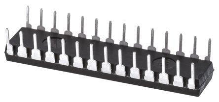
PIC18LF252

PIC18LF252 (Enhanced Flash Microcontrollers with 10-Bit A/D)

BD 7.500
PIC18LF252 come in 28-pin and 40/44-pin packages. The 28-pin devices do not have a Parallel Slave Port (PSP) implemented and the number of Analog-toDigital (A/D) converter input channels is reduced to 5. For timing-insensitive applications, the “RC” and “RCIO” device options offer additional cost savings. The RC oscillator frequency is a function of the supply voltage, the resistor (REXT) and capacitor (CEXT) values and the operating temperature. In addition to this, the oscillator frequency will vary from unit to unit due to normal process parameter variation. Furthermore, the difference in lead frame capacitance between package types will also affect the oscillation frequency, especially for low CEXT values. The user also needs to take into account variation due to tolerance of external R and C components used In the RC Oscillator mode, the oscillator frequency divided by 4 is available on the OSC2 pin. This signal may be used for test purposes or to synchronize other logic. The RCIO Oscillator mode functions like the RC mode, except that the OSC2 pin becomes an additional general purpose I/O pin. The I/O pin becomes bit 6 of PORTA (RA6). The EC and ECIO Oscillator modes require an external clock source to be connected to the OSC1 pin. The feedback device between OSC1 and OSC2 is turned off in these modes to save current. There is no oscillator start-up time required after a Power-on Reset or after a recovery from SLEEP mode In the EC Oscillator mode, the oscillator frequency divided by 4 is available on the OSC2 pin. This signal may be used for test purposes or to synchronize other logic A Phase Locked Loop circuit is provided as a programmable option for users that want to multiply the frequency of the incoming crystal oscillator signal by 4. For an input clock frequency of 10 MHz, the internal clock frequency will be multiplied to 40 MHz. This is useful for customers who are concerned with EMI due to high frequency crystals. The PLL can only be enabled when the oscillator configuration bits are programmed for HS mode. If they are programmed for any other mode, the PLL is not enabled and the system clock will come directly from OSC1. The PLL is one of the modes of the FOSC<2:0> configuration bits. The Oscillator mode is specified during device programming. A PLL lock timer is used to ensure that the PLL has locked before device execution starts. The PLL lock timer has a time-out that is called TPLL.
Choose Quantity
+ Add to Cart
Product Details
Added to cart
- There was an error adding to cart. Please try again.
Quantity updated
- An error occurred. Please try again later.
Deleted from cart
- Can't delete this product from the cart at the moment. Please try again later.